Hello firends,
List of Experiments-
- To study basic open loop and close loop control systems.
- To obtain a transient response of first order system with unit step input.
- To obtain a transient response of second order system with unit step input.
- To observe the output waveform of a underdamped system with unit step input.
- To observe the output waveform of a over damped system with unit step input.
- To observe the output waveform of a undamped system with unit step input.
- To observe the output waveform of a Critically damped system with unit step input.
- To observe the output waveform of a plant controlled by P controller.
- To observe the output waveform of a plant controlled by PI controller.
- To observe the output waveform of a plant controlled by PID controller.
Experiment No- 7
Object- To implement a PID controller for level control of a plant.
(a) To observe open loop performance of building block and calibration of PID controls
(b)To study P, PI, PID controller with type 0 system with delay.
(c) To study P, PI, PID controller with type 1 system
APPARATUS REQUIRED: PID controller setup, CRO and connecting leads.
THEORY: – The setup is designed to study performance of analog PID controller with regulated system. The board has built in signal source, DVM, simulated process and thre adjustable parameters as PID,Pfor proportional gain , I for integrated gain and D for derivative gain .three socket are given to add or out any parameter PI &D .threr are two signal sources of squire wave which is adjustable in frequency (10-40 Hz) and amplitude (0-2 Vpp) and other signal source in shape of triangular wave to sweep CRO in X-direction. One DC voltage output which is continuously variable between – 2Vand +2V.
CIRCUIT DIAGRAM:-
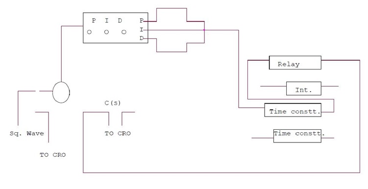
PROCEDURE:
P control mode: connect the circuit as shown in the figure. Switch over CRO for XY mode. Adjust P control to 0.1 and note the X and Y values. Increase the value of P and note the results in table. Input 1.0 Vpp , squire wave of 50ms . I not connected to adder and D control at 00. switch over CRO in tigger mode and find out period of oscillation. Switch over again in XY mode and find out percentage over shoot and steady state error
PI control mode : connect the circuit as shown in figure set Kp =reading of dial. Kd=00. input signal of squire wave amplitude = 1Vpp at 20 Hz. Switch over CRO in XY mode. Increase I in steps and note the reading . find the result of Ki for 10-15 % over shoot with minimum Ess .
PID control mode : connect the circuit as shown in figure. Input =1Vpp squire wave of same frequency adjust Kp and Ki as table 1 and 2 . increase Kd in steps and note the Ypp and Xpp output from CRO. The equation of PID controller is
M(t) = Kp e(t) +Ki e(t) dt+ Kd de / dt
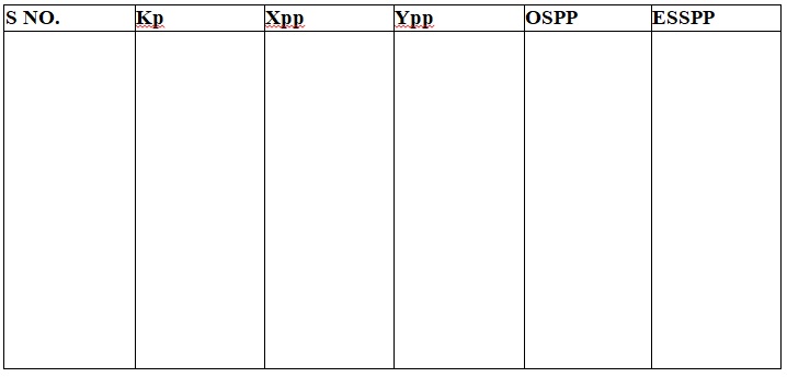
OBSERVATION TABLE :
PRECAUTIONS:
- Do not keep CRO in XY mode for long time.
- Take the reading carefully and accurately.
- Apply the required signal to the kit to avoid error.
- Switch off the kit when not in use.
Result:- PID controller for level control of a plant has been seen and studied.