Experiment No.3: To measure bending loss in optical fiber.
Object: To measure bending loss in optical fiber.
Equipments/Components: OFC kit, 1MHz Function Generator, 20 MHz Dual Trace Oscilloscope, Fiber Cable, etc
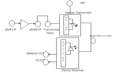
Block Diagram:
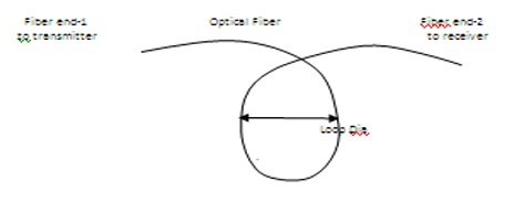
Theory: Optical fibers are available in different variety of materials. These materials are usually selected by taking into account their absorption characteristics for different wavelengths of light. In case of optical fiber, since the signal is transmitted in the form of light which is completely different in nature as that of electrons, one has to consider the interaction of matter with the radiation to study the losses in fiber. Losses are introduced in fiber due to various reasons. As light propagates from one end of fiber to another end, part of it is absorbed in the material exhibiting absorption loss. Also part of the light is reflected back or in some other directions from the impurity particles present in the material contributing to the loss of the signal at the other end of the fiber. In general terms it is known as propagation loss. Plastics fibers have higher loss of the order of 180 db/km. whenever the condition for angle of incidence of the incident light is violated the losses are introduced due to refraction of light. This occurs when fiber is subjected to bending. Lower the radius of curvature more is the loss. Other losses are due to the coupling of fiber at LED & photo detector ends.
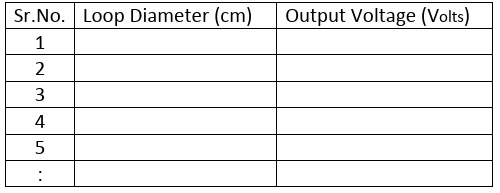
Observation Table:
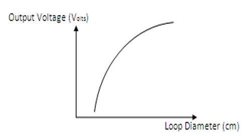
Graph:
Precautions:
- Wear safety glasses
- Avoid fiber ends
- Keep hands away from face
- Have a Well-ventilated area
- Never look into the end of a fiber cable
- Use a Power Meter
- Handle Fiber Scraps Safely
- Handle Connectors Carefully
Result: We have successfully observed fiber bending loss.