Lab Experiment No.2- To establish voice link using optical fiber.
Object: To establish voice link using optical fiber.
Apparatus: kit , CRO, Microphone, Loudspeaker (or Function generator), 1 Meter fiber cable, etc.
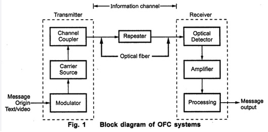
Theory: Fibre optic can be used for transmission of digital as well as analog signals. Basically, a fibre optic link contains three main elements, a transmitter, an optical fibre and a receiver. The transmitter module takes the input signal in electrical form and then transforms it into optical (light) energy containing the same information. The optical fibre is the medium, which takes the energy to the receiver. At the receiver light is converted back into electrical form with the same pattern as originally fed to the. transmitter.
Transmitter: Fibre optic transmitters are typically composed of a buffer, driver and optical source. The buffer provides both an electrical connection and isolation between the transmitter & the electrical system supplying the data. The driver provides electrical power to the optical source. Finally, the optical source converts the electrical current to the light energy with the same pattern. Commonly used optical sources are light emitting diodes (LEDs) and Laser beam.
The Transmitter section comprises of
1. Function generator.
2. Frequency modulator &
3. Pulse with modulator block.
The function generates the input signals that ere going to be used as information to through the fibre optic link. The output voltage available are 1KHz sinusoidal signal of adjustable amplitude, and fixed amplitude 1 KHz square wave signal. The modulator accepts the information signal and converts it into suitable from for transmission through the fibre optic link. The output voltages available are 1 KHz sinusoidal signal of adjustable amplitude, and fixed amplitude 1 KHz square wave signal. The modulator section accepts the information and converts it into suitable from for transmission the fibre optic link. The Fibre Optic Link: Emitter and Detector circuit on board the fibre optic link. This section provides the light source for the optic fibre and the light detector at the far end of the fibre optic links. The Optic plugs into the connectors provided in this part of the board. Two separate links are provided.
The Receiver: The Comparator circuit, Low Pass Filter Locked Loop, AC Amplifier Circuits form receiver on the board. It is able to undo the modulation process in order to recover the original information signal.
Block Diagram of OFC:
Precautions:
- Respect the minimum bend radius. Bend it too far and it’s trash.
- Clean it. Always clean the fiber after unplugging it and again before plugging it in.
- Clean the connector.
- After cleaning, apply dust caps to the fiber and to the connector.
- Store your patch cords respectfully. Putting them in zip lock bags prevents them from getting tangled. Putting them on a shelf or in a box usually prevents them from being crushed.
- Do NOT walk on them or run gear across them. Keeping them organized makes life easier too.
Result: We have successfully established a optical fiber link and seen the result.