Object: Design and realize Non Inverting amplifier using 741 Op-amp.
Apparatus Required: Bread Board, 741 IC, ±12V supply, Resistors and connecting leads.
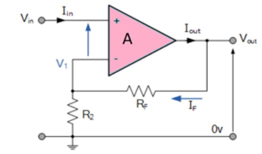
Theory: In this configuration of Op-amp the input signal is directly fed to the non inverting terminal resulting in a positive gain and output voltage in phase with input as compared to inverting Op-amp where the gain is negative and output voltage is out of phase with input , and to stabalize the circuit a negative feedback is applied through a resistor(Rf) and the inverting terminal is grounded witha input resistor(R2).This inverting Op-Amp like layout the at inverting terminal creates a virtual ground at the summing point make the Rf and R2 a potential divider accross inverting terminal, Hence determines the gain of the circuit.
Circuit Diagram:
Observations:
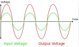
1. Observe the output waveform from CRO. An inverted and amplified waveform will be observed.
2. Measure the input and output voltage from the input and output waveform in the CRO.
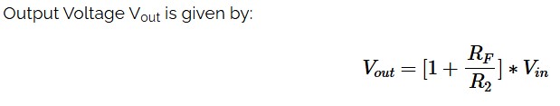
3. Calculate : Vo=(1+Rf/R1)*Vi
4. Compare the theoretical voltage gain from the above equation with the experimental value obtained by dividing output voltage by input voltages observed.
5. Observe outputs of the inverting amplifier circuit using different input waveforms.
R1=10k and Rf=R2=100k
Vo=(1+Rf/R1)*Vi
Waveform:
Result: Hence the opamp can configure as non inverting amplifier circuit as observed from the output waveforms.
Precautions:
1. Connections should be verified before clicking run button.
2. The resistance to be chosen should be in Kohm range.
3. Best performance is being obtained within 50Hz to 1Mhz.