Object: To study Splicing and its preperation.
Apparatus required: Arc fusion splicer, Variable voltage power supply, wire stripper, Cleaver
Theory: Splicing optical fiber cable (OFC) is the process of joining two fibers to create a longer, permanent link for long-distance data transmission. The two main methods are fusion splicing, where fibers are fused with an electric arc for a high-quality, low-loss permanent splice, and mechanical splicing, where fibers are aligned and held together with a mechanical connector, often used for emergency repairs. Proper splicing requires precise alignment, cleaning, and preparation of the fibers to ensure minimal signal loss
Fiber optics technology is not “perfect” because some light is lost as it travels down the optical core. Light loss inside the fiber, or attenuation, is called “intrinsic” loss. This intrinsic loss can be categorized as either scattering or absorption. Fiber optics system cannot always be installed with a single uninterrupted length of optical fiber. Often, two or more fiber length must be joined in order to obtain a necessary length, or route through buildings and enclosures. Losses from these connections are called “extrinsic loss” because they occur outside the optical fiber core and cladding boundary. The two most common extrinsic losses due to joining or connecting optical fiber occur at:
- Splices- Permanent connections of two optical fiber length that may be thermally fused or mechanically applied.
- Connectors-Junctions that allow an optical fiber to be readily attached or detached from a light source, detector or another fiber.
Steps for Splicing:
- Inserting Power Supply into Splicer
- Turning splicer ON
- Setting sleeve centering device
- Cleaning optical fiber
- Placing protection sleeve over the fiber. Protection sleeve over the fiber
- Stripping and cleaning fiber
- Fiber Cleaving
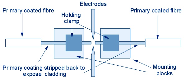
- Place Loading fiber into splicer : Open wind protector and sheath clamps, Place prepared fiber onto v-groove so that the fiber tip is located between the v-groove edge and tip of the electrode, Hold the fiber with fingers and close sheath clamp so that the fiber does not move. If the fiber is not placed properly reload the fiber, Load another fiber in the same manner as above. Close wing protector
Diagram:
Result: We have studied splicing and its preperation.