Lab Manual:-Experiment No-3: Pulse Code Modulation
Objective:
To study and demonstrate the working of Pulse Code Modulation (PCM) technique.
Apparatus Required:
• PCM Trainer Kit / Module
• Function Generator (Sine wave)
• Cathode Ray Oscilloscope (CRO)
• Connecting Wires / Patch Cords
• Power Supply
Theory:
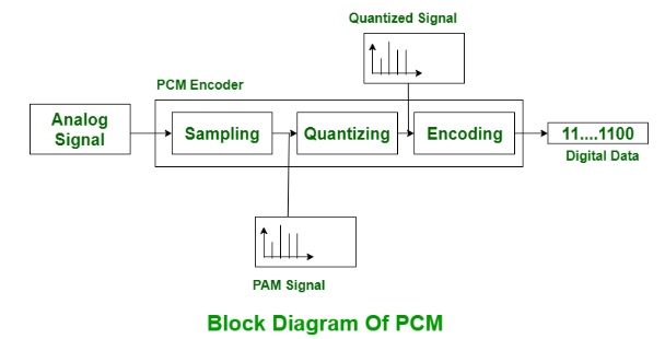
Pulse Code Modulation (PCM) is a digital modulation technique used in communication systems. In PCM, the analog input signal is first sampled, then quantized into discrete levels, and finally encoded into a binary format for transmission. It offers advantages like noise immunity, better signal quality, and efficient multiplexing.
Block Diagram:
Procedure:
• Connect the PCM Trainer Kit as per the block diagram.
• Apply an analog sine wave input (e.g., 1 kHz) using the function generator.
• Observe the sampled signal on the CRO.
• Note the quantized steps and binary PCM output.
• At the decoder, observe the reconstructed signal.
• Compare the input and output waveforms.
Observations:
Example parameters (fill actual values during experiment):
– Input Signal Frequency: 1 kHz
– Sampling Frequency: 8 kHz
– Number of Quantization Levels: 16
– Bit Rate: 32 kbps
Result:
The Pulse Code Modulation system was successfully demonstrated. The encoded PCM signal was observed and the analog signal was reconstructed effectively.
Conclusion:
PCM is a reliable and widely used digital modulation method. It helps in transmitting analog signals in digital form with high noise immunity.
Viva Questions:
1. What is Pulse Code Modulation?
2. Why is quantization required in PCM?
3. What is the Nyquist sampling theorem?
4. List advantages and disadvantages of PCM.
5. How is PCM different from Delta Modulation?