Lab Manual:-Experiment No-4: Pulse Amplitude Modulation
Objective:
To study and demonstrate the working of Pulse Amplitude Modulation (PAM) technique.
Apparatus Required:
• PAM Trainer Kit / Module
• Function Generator (Sine wave)
• Cathode Ray Oscilloscope (CRO)
• Connecting Wires / Patch Cords
• Power Supply
Theory:
Pulse Amplitude Modulation (PAM) is a modulation technique in which the amplitude of regularly spaced pulses varies according to the instantaneous value of the analog message signal. PAM is one of the simplest forms of pulse modulation and is widely used in digital communication systems. In practical systems, PAM serves as a basis for more complex modulation techniques like PCM and PWM.
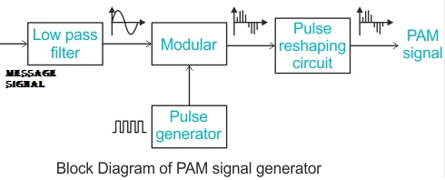
Block Diagram:
Waveform:

Procedure:
• Connect the PAM Trainer Kit as per the block diagram.
• Connect the function generator and generate a sine wave input (e.g., 1 kHz).
• Observe the analog signal and pulse train input to the modulator on the CRO.
• Observe the output PAM waveform on the CRO.
• Note how the amplitude of each pulse follows the analog input signal.
• At the receiver side, observe the filtered output signal and compare it with the original analog input.
Observations:
Fill in the following parameters based on your readings:
– Input Signal Frequency: __________
– Pulse Repetition Frequency: __________
– Modulation Depth: __________
– PAM Output Waveform Shape: __________
Result:
The Pulse Amplitude Modulation system was successfully demonstrated. The amplitude of the pulses varied in accordance with the input analog signal.
Conclusion:
PAM is a basic pulse modulation technique and provides a foundation for understanding more advanced systems. It enables the representation of an analog signal in discrete-time form.
Viva Questions:
1. What is Pulse Amplitude Modulation (PAM)?
2. How is PAM different from PWM and PPM?
3. What are the applications of PAM?
4. What is the role of the low-pass filter at the receiver end?
5. What are the limitations of PAM in communication systems?