Linear Integrated Circuit: Experiment No:1 Design and realize Inverting amplifier using 741 Op-amp.
Object: Design and realize Inverting amplifier using 741 Op-amp.
Apparatus Required: Bread Board, 741 IC, ±12V supply, Resistors and connecting leads.
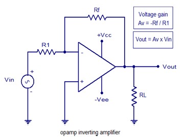
Theory: An inverting amplifier using op-amp is a type of amplifier using op-amp where the output waveform will be phase opposite to the input waveform. The input waveform will be amplifier by the factor Av (voltage gain of the amplifier) in magnitude and its phase will be inverted. In the inverting amplifier circuit the signal to be amplified is applied to the inverting input of the opamp through the input resistance R1. Rf is the feedback resistor. Rf and Rin together determine the gain of the amplifier. Inverting operational amplifier gain can be expressed using the equation Av = – Rf/R1. Negative sign implies that the output signal is negated. The circuit diagram of a basic inverting amplifier using op-amp is shown below-
Circuit Diagram:
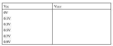
Observation:
1. Observe the output waveform from CRO. An inverted and amplified waveform will be observed.
2. Measure the input and output voltage from the input and output waveform in the CRO.
3. Calculate
/equation1.PNG)
4. Compare the theoretical voltage gain from the above equation with the experimental value obtained by dividing output voltage by input voltages observed.
5. Observe outputs of the inverting amplifier circuit using different input waveforms.
R1=10k and Rf=R2=100k
Vo=(-Rf/R1)*Vi
Waveform:
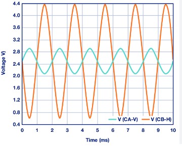
Result:
Hence the opamp can configure as inverting amplifier circuit as observed from the output waveforms.
Precautions:
1. Connections should be verified before clicking run button.
2. The resistance to be chosen should be in Kohm range.
3. Best performance is being obtained within 50Hz to 1Mhz.