
Object:
To verify the Maximum Power Transfer Theorem by varying the load resistance and observing the power delivered to the load.
Apparatus Required:
Regulated DC power supply (12 V), resistors (1 kΩ and suitable load-resistance decade box or resistors), digital multimeter(s), breadboard/trainer board, connecting wires.
Theory:
The Maximum Power Transfer Theorem states that a linear DC network delivers maximum power to a load when the load resistance equals the Thevenin resistance of the network as seen from the load terminals: RL = Rth. For a Thevenin source Vth in series with Rth, load current IL = Vth/(Rth + RL), load voltage VL = IL × RL, and load power PL = VL²/RL = IL²RL.
For AC networks, maximum average power transfer occurs when the load impedance is the complex conjugate of the Thevenin impedance. This experiment uses a resistive DC circuit.
Circuit Diagram:
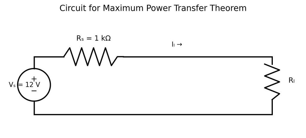
Use a 12 V DC source with a 1 kΩ series resistance and vary RL. The load voltage is measured across RL; load current may be measured in series or calculated from VL/RL.
Thevenin Equivalent:
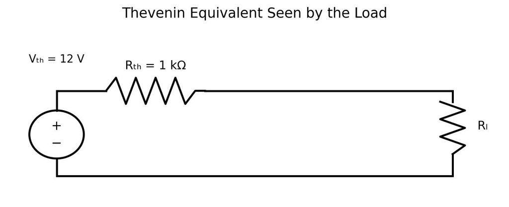
For this circuit, Vth = 12 V and Rth = 1 kΩ. Therefore, maximum power is expected when RL = 1 kΩ.
Procedure:
- Keep the DC supply OFF while making connections. Assemble the circuit as shown in the diagram.
- Set the regulated DC supply to 12 V and verify the polarity before switching it ON.
- Set the load resistance RL to 500 Ω. Measure and record the voltage VL across the load.
- Repeat the measurement for each RL value listed in the observation table.
- For each reading, calculate IL = VL/RL and PL = VL²/RL. If current is measured directly, record it and use it to calculate PL = IL²RL.
- Compare the calculated load power for all load resistances and identify the resistance at which power is maximum.
- Switch OFF the supply before changing circuit connections.
Observation Table:
Supply voltage Vs = 12 V; series resistance Rs = 1 kΩ. The table below contains theoretical/expected values for guidance, not actual laboratory measurements.
| S. No. | Load RL (Ω) | Load current IL (mA) | Load voltage VL (V) | Load power PL (mW) |
| 1 | 500 | 8.00 | 4.00 | 32.00 |
| 2 | 750 | 6.86 | 5.14 | 35.27 |
| 3 | 1,000 | 6.00 | 6.00 | 36.00 |
| 4 | 1,500 | 4.80 | 7.20 | 34.56 |
| 5 | 2,200 | 3.75 | 8.25 | 30.94 |
| 6 | 3,300 | 2.79 | 9.21 | 25.70 |
Sample Calculation (RL = 1 kΩ):
IL = Vs/(Rs + RL) = 12/(1000 + 1000) = 0.006 A = 6 mA
VL = IL × RL = 0.006 × 1000 = 6 V
PL = VL²/RL = 6²/1000 = 0.036 W = 36 mW
Result:
Theoretical results show that the load receives maximum power when RL = Rth = 1 kΩ. At this point, VL = 6 V, IL = 6 mA, and PL = 36 mW. Verify this experimentally using measured readings.
Precautions:
- Check all connections and polarity before switching ON the supply.
- Use the correct meter range and connect the voltmeter in parallel with RL.
- If measuring current directly, connect the ammeter in series; never connect an ammeter directly across the supply.
- Switch OFF the supply before changing the load resistance.
- Use resistors with suitable power ratings and avoid touching components that may become hot.
- Do not record theoretical values as measured observations.
Viva-Voce Questions:
- State the Maximum Power Transfer Theorem.
- What is Thevenin resistance?
- What is the condition for maximum power transfer in a DC resistive circuit?
- What is the maximum load power for the circuit used in this experiment?
- How does load power change when RL is much smaller or much larger than Rth?
- State the maximum power transfer condition for AC circuits.
- Does maximum power transfer also mean maximum efficiency? Explain briefly.
Note: For a purely resistive Thevenin source, maximum power transfer occurs at RL = Rth. At this condition, the ideal source resistance dissipates the same power as the load, so efficiency is 50%.