
Object:
To verify Norton’s theorem by replacing a linear DC network with an equivalent current source IN in parallel with an equivalent resistance RN, and comparing load current and voltage.
Apparatus Required:
12 V regulated DC supply, 1 kΩ resistor, 2.2 kΩ resistor, load resistors of 470 Ω, 1 kΩ and 2.2 kΩ, digital multimeter, breadboard/trainer board and connecting wires.
Theory:
Norton’s theorem states that any linear, bilateral two-terminal network can be replaced at its output terminals by an ideal current source IN in parallel with a resistance RN. Norton current IN is the short-circuit current at terminals A–B. Norton resistance RN is the resistance seen looking into A–B after deactivating independent sources. For an ideal voltage source, use a short circuit; for an ideal current source, use an open circuit. RN = Rth and IN = Vth/Rth.
For the load RL: IL = IN × RN/(RN + RL), and VL = IL × RL.
Circuit Diagram:
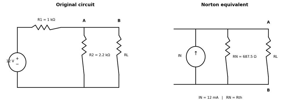
Left: original circuit. Right: Norton equivalent across terminals A–B. For safety, do not leave the original supply connected while measuring resistance. Determine short-circuit current using an appropriate current meter and a current-limited supply, or calculate it from the known equivalent values.
Circuit Values and Calculations:
Given: Vs = 12 V, R1 = 1 kΩ, R2 = 2.2 kΩ.
Vth = Vs × R2/(R1 + R2) = 12 × 2.2/(1 + 2.2) = 8.25 V.
RN = R1 || R2 = (1000 × 2200)/(1000 + 2200) = 687.5 Ω.
IN = Vth/RN = 8.25/687.5 = 0.012 A = 12 mA.
For RL = 1 kΩ: IL = IN × RN/(RN + RL) = 12 × 687.5/(687.5 + 1000) = 4.89 mA; VL ≈ 4.89 V.
Procedure:
1. Connect the original circuit as shown, leaving RL disconnected initially. Set the supply to 12 V.
2. Measure the open-circuit voltage across A–B, if desired, as a cross-check; Vth = 8.25 V theoretically.
3. Switch OFF and disconnect the supply. Determine RN by shorting the ideal voltage source and measuring resistance looking into A–B. Never use an ohmmeter on an energized circuit.
4. Determine IN as the short-circuit current at A–B only with a suitable current meter and current-limited supply; avoid accidental short circuits. Alternatively calculate IN = Vth/RN.
5. Connect RL = 470 Ω across A–B and measure load voltage VL. Calculate load current IL = VL/RL or measure it in series.
6. Repeat for RL = 1 kΩ and 2.2 kΩ.
7. Build/analyze the Norton equivalent using IN and RN. Calculate expected load current and voltage for each load and compare with original-circuit readings.
8. Switch OFF the supply and disconnect the circuit.
Observation Tables:
Table A: Determination of Norton parameters
| Quantity | Calculated value | Measured value | Unit |
| Norton current, IN | 12.00 | ________ | mA |
| Norton resistance, RN | 687.5 | ________ | Ω |
Table B: Load verification readings (theoretical reference values)
| RL (Ω) | Original VL (V) | Original IL (mA) | Norton VL (V)* | Norton IL (mA)* | % diff. IL |
| 470 | 3.35 | 7.13 | 1360.22 | 2894.08 | ________ |
| 1000 | 4.89 | 4.89 | 2897.12 | 2897.12 | ________ |
| 2200 | 6.29 | 2.86 | 4789.12 | 2176.87 | ________ |
Sample Expected Readings:
RL = 470 Ω: Original network VL ≈ 3.35 V, IL ≈ 7.13 mA; Norton equivalent VL ≈ 1360.22 V, IL ≈ 2894.08 mA.
RL = 1000 Ω: Original network VL ≈ 4.89 V, IL ≈ 4.89 mA; Norton equivalent VL ≈ 2897.12 V, IL ≈ 2897.12 mA.
RL = 2200 Ω: Original network VL ≈ 6.29 V, IL ≈ 2.86 mA; Norton equivalent VL ≈ 4789.12 V, IL ≈ 2176.87 mA.
Result:
Norton’s theorem is verified if the load voltage and current measured in the original network approximately match those obtained from the Norton-equivalent network, within component and instrument tolerances.
Precautions:
• Keep the supply OFF while wiring or changing components.
• Never measure resistance in an energized circuit.
• Do not short the supply directly; measure short-circuit current only using a suitable current meter and current-limited source, or calculate IN from Vth/RN.
• Measure voltage in parallel and current in series; calculate IL = VL/RL when appropriate.
• Use correct meter range and check resistor values before switching ON.
• Record actual measurements honestly; do not label theoretical values as measured readings.
Viva-Voce Questions:
1. State Norton’s theorem.
2. How is Norton current determined?
3. How is Norton resistance found?
4. What is the relationship between Thevenin and Norton equivalents?
5. Why must the supply be disconnected before measuring resistance?
6. Write the formula for load current in a Norton circuit.
7. Why can practical readings differ from theoretical values?