Linear Integrated Circuit: Experiment No: 4 Study of Differentiator using Operational Amplifier.
Object: Study of Differentiator using Operational Amplifier.
Apparatus Required: Bread Board, 741 IC, ±12V supply, Resistors, Capacitor and connecting leads.
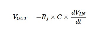
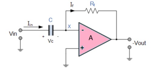
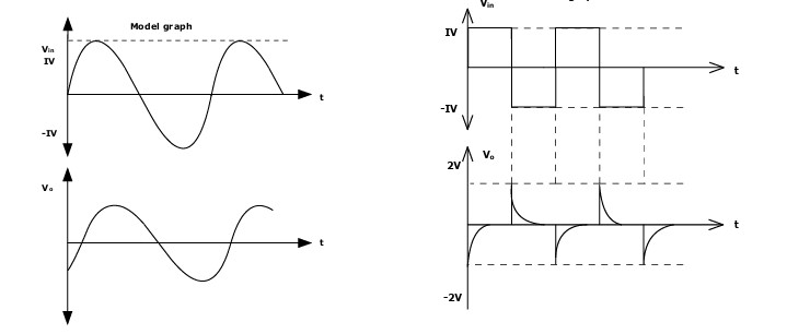
Theory: In the differentiator circuit the input is connected to the the inverting output of the Op-Amp through a capacitor(C) and a negetive feedback is provided to the inverting input terminal through a resistor(Rf), which is same as an integrator circuit with feedback capacitor and input resistor being replaced with each other. Here the circuit performs a mathematical differentiation operation, and the output is the first derivative of the input signal, 180′ out of phase and apmlified with a factor Rf*C. The capacitor on the input allows only the AC component and restrict the DC, at low frequency the reactance of capicitor is very high causing a low gain and high frequency vice varsa but and high frequency the circuit becomes unstable.
Output Voltage:
Circuit Diagram:
Values of Components:
Let C = 0.01µF
Then Rf = 15KΩ
Let Ri = Rf/10 = 1.5KΩ
Procedure:
- Connections are given as per the circuit diagram.
- + Vcc and – Vcc supply is given to the power supply terminal of the Op-Amp IC.
- By adjusting the amplitude and frequency knobs of the function generator, appropriate
input voltage is applied to the inverting input terminal of the Op-Amp. - The output voltage is obtained in the CRO and the input and output voltage waveforms
are plotted in a graph sheet.
Waveform:
Precautions:
- Add Series Input Resistor
- Add Parallel Feedback Capacitor
- Avoid Step Inputs
- Connect Power First
- Verify Polarity
Result: The design of the Differentiator circuit was done and the input and output waveforms were obtained.